
Custom Rotational Molding Project Review
Plasticpartsmfg reviews custom rotational molding requirements for hollow plastic parts, large enclosures, tanks, containers, covers, and low- to medium-volume components. Based in Shenzhen, China, we support engineering teams from tooling planning and material selection through finishing and final inspection.
Send your CAD files, drawings, or sample photos. We assess geometry, wall distribution, tooling economics, and alternative processes like injection molding to find the most cost-effective path forward.
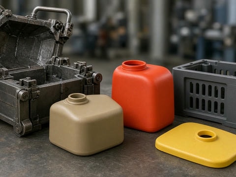
Is Rotational Molding Suitable for Your Part?
Rotational molding creates hollow plastic components by placing polymer powder inside a heated mold that slowly rotates multi-axially. As resin coats the hot mold cavity without high injection pressure, it produces low-stress, seamless products with cost-effective tooling.
Ideal Component Profiles
- • Hollow tanks, storage containers, fluid reservoirs, and buoyancy floats
- • Large heavy-duty bins, transit cases, ducts, and protective equipment covers
- • Playground equipment, recreational items, and agricultural components
- • Low-to-medium volume enclosures where high-tonnage tooling is cost-prohibitive
Process Constraints to Consider
- • Not suitable for ultra-thin wall profiles or high precision tight-tolerance demands
- • Cannot easily form miniature structural ribs, fine clips, or intricate snap-fits
- • Longer heating/cooling cycles require review for ultra-high-volume supply lines
- • Wall thickness naturally varies slightly across complex internal radiuses
Custom Rotational Molding Parameters
Planning guide for custom projects. Exact specifications are verified through part CAD geometry, functional requirements, and chosen resin grades during initial RFQ review.
| Project Item | Typical Planning Range or Option |
|---|---|
| Part Structure | Hollow, single-wall, or molded hollow enclosure designs |
| Common Materials | LLDPE, HDPE, PP, PA (Nylon), PVC, and selected cross-linked elastomers |
| Typical Wall Thickness | Approx. 2.5–12 mm, depending on material grade, size, and geometry |
| Wall Thickness Control | Dependent on powder distribution, corner radii, and multi-axis rotation profiles |
| Tooling Materials | Cast or CNC machined aluminum, fabricated sheet steel, or hybrid tooling |
| Surface Finishes | Mold texture, matte, gloss, molded-in graphics, integrated color matching |
| Embedded Inserts | Threaded brass/steel inserts, bushings, support plates, and molded-in fittings |
| Typical Tolerancing | Generally looser than high-pressure tooling; confirm via 2D engineering drawings |
| Production Quantities | Pilot prototypes, low-volume batch production, and repeatable scheduled runs |
| Secondary Operations | Routing, drilling, CNC trimming, hardware assembly, pressure testing, packaging |
What We Review Before Quoting
A viable quotation goes beyond gross envelope dimensions. Our technical analysis uncovers potential production risks, material trade-offs, and mold life considerations upfront.
Geometry & Structural Feasibility
We check the internal hollow cavity, draft angles, and natural flow of polymer powder during rotation to avoid unformed areas or heavy sinks.
- ✓ Internal corners, radii, draft, and wall transitions
- ✓ Large flat panels prone to warpage or oil-canning
- ✓ Stiffening ribs, handle pockets, and mounting features
- ✓ Cut-out areas, trim lines, and machining allowances
Design Tip
Generous radii (typically R5 or greater) allow rotationally molded powders to bridge naturally along edges. Sharp right angles often lead to thin spots, pinholes, and internal structural voids.
End-to-End Plastic Manufacturing Support
Plasticpartsmfg evaluates the complete project life cycle, from tooling feasibility to post-process operations and assembly.
Process Assessment
Comparing rotational molding, injection molding (50–650T range), and insert molding based on production quantities, precision, and investment scale.
Mold Development
Comprehensive CAD reviews to avoid undercuts, resolve difficult parting lines, configure thermal venting, and position mold cores reliably.
Finishing & Assembly
Secondary CNC trimming, deburring, brass hardware installation, pad printing, surface coating, subassembly, and export-grade custom packing.
Inspection Control
Inspection against 2D/3D datums, wall thickness checks via ultrasonic gauge, pressure leak testing, cosmetic verification, and sample sign-off.
Rotational Molding or Injection Molding?
Selecting the correct manufacturing path balances tooling capital, unit economics, wall structure, and geometric detail. We help you choose the right process before mold steel is cut.
| Requirement | Rotational Molding May Fit | Injection Molding May Fit |
|---|---|---|
| Part Structure | Large, seamless, hollow or double-wall structures | Solid, thin-wall, or highly intricate details |
| Tooling Investment | Significantly lower upfront mold costs | Substantial mold investment, particularly for large parts |
| Part Size Capabilities | Excellent for oversized shells, large containers, and tanks | Constrained by machine platen size and shot capacity |
| Dimensional Tolerances | Moderate tolerances for functional designs | High-precision, repeatable tight tolerances |
| Production Volume | Low to medium volumes (e.g., hundreds to low thousands) | High volumes with rapid cycle times |
| Wall Characteristics | Thicker, relatively uniform hollow outer shells | Thin walls with fine ribs, bosses, and molded snap-fits |
| Post-Process Operations | Manual/CNC edge routing, trimming, and drilling | Most features and holes are net-molded directly |
Design Guidelines for Rotational Molding
Because rotational molding relies on powder sintering rather than high-pressure cavity injection, following core rotational design guidelines prevents unexpected defects.
Applications We Review & Manufacture
Plasticpartsmfg evaluates custom hollow and enclosure products across multiple commercial and industrial sectors:
Submit Your CAD Files for a Custom RFQ
For an accurate engineering and manufacturing review, please provide details on geometry, functional demands, and project volume.
Recommended Submission Details
- 1. CAD files (STEP, STP, IGES) and 2D drawings with tolerance requirements
- 2. Target resin preference, operating environment, and UV exposure
- 3. Estimated prototype batch and ongoing production quantities
- 4. Requirements for hardware inserts, custom surface textures, or assembly
- 5. Delivery destination and project schedule targets
Request a Project Assessment
Submit your RFQ information below. Our technical engineering team will review the geometry and reply with DFM feedback and tooling quotations.